Saturday, November 10, 2012

Compile Octave using 16/32 bits colour - Ubuntu


  Hello there,

  This post is a little different of I'm using to write, but yet very useful for us engineers! It's about how to compile octave to be able to load 16 or 32 bits colour images. First of all, what's Octave?
  Octave is a gnu version of Matlab (and it almost compatible with it. Actually most of commands are identical, so migrating for Matlab to Octave should not be very hard. The official site is here!
  Ok, what's the problem? The problem is that Octave uses GraphicsMagick (an image processing program) and by default it comes configured in 8bits in Ubuntu. So, we need to recompile GraphicsMagick to use 16 or 32 bits and then recompile Octave with the new GraphicsMagick. I'm using Ubuntu 12.04, Octave-3.6.3 and GraphicsMagick-1.3.12.
  Here you are the steps:
  1) Download all packages needed.
sudo apt-get install g++ gcc gfortran make libblas-dev liblapack-dev libpcre3-dev libreadline-dev libarpack2-dev libcurl4-gnutls-dev libfftw3-dev libfltk-dev libfontconfig1-dev libfreetype6-dev libglpk-dev libgraphicsmagick++-dev gnuplot libhdf5-serial-dev libgl-dev libqhull-dev libqrupdate-dev libsuitesparse-dev texinfo zlib1g-dev libgraphicsmagick++1-dev libgraphicsmagick++3
  2) Download GraphicsMagick source from Ubuntu repository
wget https://launchpad.net/ubuntu/precise/+source/graphicsmagick/1.3.12-1.1build1/+files/graphicsmagick_1.3.12.orig.tar.gz
  3) Configure and install GraphicsMagick.If you want 16 bits set --with-quantum-depth=16!
tar zxvf graphicsmagick_1.3.12.orig.tar.gz
cd GraphicsMagick-1.3.12
./configure  --with-quantum-depth=32 --enable-shared --disable-static --with-magick-plus-plus=yes
make
sudo make install
  4) Set GraphicsMagick libs path
export PATH=$PATH:/usr/local/lib
  5) Download Octave
wget ftp://ftp.gnu.org/gnu/octave/octave-3.6.3.tar.gz
  6) Configure and install Octave
tar zxvf octave-3.6.3.tar.gz
cd octave-3.6.3
./configure --prefix=/usr/local/octave  --with-blas="-L/usr/lib -lblas" --with-lapack="-L/usr/lib -llapack" --with-fftw3f-libdir=/usr/local/fftw/lib --with-fftw3-includedir=/usr/local/fftw/include --without-curl --enable-shared --disable-static
make
sudo make install
  Here some links that can help you if you have any problems:
GraphicsMagick wiki
Discussed in forum

  Bye
 Marcelo
Read more ►

Saturday, September 8, 2012

STM32F0 discovery + GCC + Eclipse + OpenOCD + Ubuntu - Part II

  Hello!
  As promissed in last post, I'll show you how to setup eclipse to work with the our STM32F0 discovery board + open source toolchain.

1) Open eclipse. First of all we need to install (if not already installed) two new software. So go to menu Help/Install New Software. In work with, type "http://download.eclipse.org/tools/cdt/releases/juno" and in the list below choose CDT Optional Features/ C/C++ GDB Hardware Debugging". Next in http://gnuarmeclipse.sourceforge.net/updates, select "GNU ARM C/C++ Development Support".
  2) Create a new C Project. Go to menu File/New Project and select C/C++ - C Project. Click next.
  3) In next window Choose under ARM Cross Target Application - Empty project. Select your toolchain (Sourcery G++ Lite) or (GNUARM).

  4) Go to menu Project/Properties. In C/C++ Build / Settings select Tool settings. In Target Processor change "Processor" to cortex-m0.


  5) Now in the same Tool Settings tab go to ARM Sourcery Linux GCC C Compiler / Preprocessor and add the following values:
USE_STDPERIPH_DRIVER
USE_STM32F0_DISCOVERY
STM32F0XX


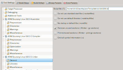
  6) Still in Tool Settings tab go to ARM Sourcery Linux GCC C Linker / General and  uncheck "Do not use standard start file (-nostartfiles) and check "Remove unused sections (-Xlinker --gc-sections). In Script file (-T) set path: /home/stm32/workspace/Template/src/stm32f0.ld


  7) In C/C++ General, select Path and Symbols and add the following paths (in both Assembly and GNU C): 
/Template/Libraries/CMSIS/ST/STM32F0xx/Include
/Template/Libraries/
/Template/src
/Template/Libraries/STM32F0xx_StdPeriph_Driver/inc
/Template/Libraries/CMSIS/Include


  8) Configure GDB by clicking in the small arrow in the right of the bug. Select "Debug Configurations... ". Select "GDB Hardware Debugging" right click and select new. Change name to GDB-OpenOCD and in the bottom of the window click in "Select other..." and select "GDB (DSF) Hardware Debugging Launcher".

 9) Under tab Debugger, uncheck everything and set the path of your gdb from your toolchain:  /home/user/stm32/gcc-arm-none-eabi/bin/arm-none-eabi-gdb

  10) Under tab Start Up, uncheck everything and in "Run commands" add:
target remote localhost:3333
monitor reset init 
monitor stm_flash /home/user/stm32/workspace/Template/Debug/Template.elf 
load /home/user/stm32/workspace/Template/Debug/Template.elf 
symbol-file /home/user/stm32/workspace/Template/Debug/Template.elf 
cont

  11) Now configure OpenOCD by clicking in the small arrow in the right of the play with toolbox (external tools). Select "External Tool Configurations... ". Select "Program" right click and select new. Change name to OpenOCD. Set openocd path: /usr/bin/openocd and working directory: /home/user/stm32/openocd-0.6.0-rc1/tcl
  In "Arguments" write: -f /home/user/stm32/workspace/Template/extra/stm32f0discovery.cfg -f /home/user/stm32/workspace/Template/extra/stm32f0-openocd.cfg

  If everything is OK, compile your hello world program. Go to "External Tools" and select "OpenOCD". It should show de following message in Console:

Open On-Chip Debugger 0.6.0-rc1 (2012-09-03-20:37)
Licensed under GNU GPL v2
[...]


  Now, the great moment, put a breakpoint in your main and select the bug icon "GDB - OpenOCD". It should stop your code like this:


  That's all for today!

  Marcelo

Read more ►

Wednesday, August 22, 2012

Digikey - 180 days of education

  Hello there!

  This post I'd like to comment a little bit about the digikey continuing education program. It's 180 days of education in electronics, firmware, concepts, good practices in R&D, tests, etc. For those who missed the others class, we can listen to all archived classes. There plenty of differents topics like

  • Introduction to electronics
  • Linux kernel debugging
  • Basics of software-based test systems
  • Testing wireless devices & systems
  For archived classes click here!
  In these days they are discussing about ARM Cortex-M0 and in the next few days it will be about Embedded Computer Vision. 


  Everything is free!

  Bye

  Marcelo
Read more ►

Saturday, August 18, 2012

STM32F0 discovery + GCC + Eclipse + OpenOCD + Ubuntu - Part I

Hello there!

In this post I'll show how to set up your IDE to debug the STM32F0 discovery board using open source tools.
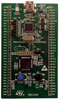
The STM32F0 is a kit (very cheap) from ST micro to introduces the ARM Cortex - M0. This little boards has integrated a STM32F051R8T6 microcontroller with a button, leds and I/Os and also a st-linkV2 which is used to program and debug. That's why this little board is so amazing! We can use the st-linkV2 embedded to program and debug others microcontrollers, you need only to change two jumpers and we're ready!

I must say that everything I did here was based in what Mike Szczys did here. So THANK YOU Mike!!!
Ok, let's start! First of all, create a folder stm32 in your home. We'll use this folder to save all files.

mkdir /home/stm32

1) Installing basic tools
sudo apt-get install build-essential
sudo apt-get install git
sudo apt-get install libtool
sudo apt-get install libftdi1
sudo apt-get install texinfo

2) Installing toolchain
a) You can download toolchain from code sourcery (or if you prefer, you can use crosstool-ng and generate your own toolchain)
https://sourcery.mentor.com/sgpp/lite/arm/portal/subscription?@template=lite

b) Install toolchain
sh ./arm-2012.03-56-arm-none-eabi.bin

if you have the error "ERROR: DASH shell not supported as system shell", type
sudo dpkg-reconfigure -plow dash

c) Chose: Minimal installation, default folder, check "Modify path for user", check "Don't create links"

3) Installing OpenOCD
Get here the latest version of OpenOCD (I got openocd-0.6.0-rc1) and save

tar jxvf openocd-0.6.0-rc1.tar.bz2
cd openocd-0.6.0-rc1
./configure --prefix=/usr --enable-maintainer-mode --enable-stlink
make
sudo make install

4) Install udev rules
git clone git://github.com/texane/stlink.git
cd /home/stm32/stlink
sudo install -m 644 49-stlinkv2.rules /etc/udev/rules.d/49-stlinkv2.rules
sudo udevadm control --reload-rules

5) Install Eclipse
a)Get the latest version Eclipse C/C++ here. My version is Indigo.
b) Install plugins. Go to Help/Install New Software...
c) Work with: http://gnuarmeclipse.sourceforge.net/updates and chose GNU ARM C/C++ Developement Support. Install it.
d) Work with: http://download.eclipse.org/tools/cdt/releases/indigo and chose GDB hardware debugging. Install it.

6) Get templates and setting up file directory
a) Create a workspace, a Template and a src folder inside at /home/stm32 (or somewhere)
mkdir /home/stm32/workspace
mkdir /home/stm32/workspace/Template
mkdir /home/stm32/workspace/Template/src

b) Download the following templates:
STM32F0discovery_fw.zip
git clone https://github.com/szczys/stm32f0-discovery-basic-template.git

b) Unzip STM32F0discovery_fw.zip and copy the Libraries folder into /home/stm32/workspace/Template
c) Copy STM32F0-Discovery_FW_V1.0.0/Project/Demonstration/stm32f0xx_conf.h into src folder.
d) Copy and paste the files in stm32f0-discovery-basic-template/Device/ldscripts/ into src folder.
e) Edit stm32f0.ld in src folder. Change paths in both include:
INCLUDE "/home/stm32/workspace/Template/src/stm32f0discovery_def.ld"INCLUDE "/home/stm32/workspace/Template/src/sections_flash.ld"f) Copy stm32f0-discovery-basic-template/Device/startup_stm32f0xx.s into src folder. RENAME IT TO .S. It's an eclipse issue.
g) Copy folder stm32f0-discovery-basic-template/Extra to /home/stm32/workspace/Template/


This post is already too long. In next post I'll show how to start a new project and set up debugger and OpenOCD in Eclipse. I promise that it will be soon!

Bye

Marcelo
Read more ►

Saturday, July 21, 2012

Philip Koopman - Better Embedded System Software Review

  Hello there!
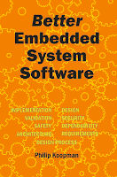
  This post is a review of Philip's book - Better Embedded System Software. I was looking for a book where I could learn a little more about the processes of making an embedded system project or how improve my designs, improve the management of my projects, etc. I wasn't looking for something big or "complicated" as PMBOK, so I found this wonderful book.
  Although the word Software in its title, you can use most of all suggestions to your hardware design too.


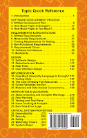
The book covers the following topics: system development plan,  requirements,  architecture,  design,  implementation and test plans. For every topic the author give us the bad symptoms if we are not doing a good job or doing in an incorrectly manner, the risks if we continue doing in that way, how to improve or correct our management and the pitfalls to follow his suggestions. Everything with lots of good practices and good ideas.
  I think that this book is intend for people who has already a good background in development and want to improve a little more in project management. Once I mainly worked in small and medium companies, I always notice that in those companies we weren't very organized or they didn't have a methodical approach to design and that was the cause of many problems and bugs that could be solved before they happened.
  At the beginning I though that this book was a little expensive but after reading it I realized that it worth every penny payed.


  Marcelo
Read more ►

Tuesday, June 5, 2012

Michael Barr - Embedded C Coding Standard - Review

  Hello there!
  This post is a review of Michael Barr's Embedded C Coding Standard book.
  First of all, why a c coding standard? I have been working in my life in small and medium companies and in most of them, we always had the same problem. No c coding standard. Everyone had their own standard and very often, those standard are not standard, because it used to change every project. Every time some one quit the company, it's always the same problem: code badly written, no comments, hard to read, hard to understand and overall hard to maintain.
  So this book is a very good start point for those who works in a company which doesn't have a standard and want to deploy one.
  First Michael Barr make clear that the code written is a property of the company and not of the programmer. A standard code eliminates conflict over items that are sometimes viewed as personal stylistic preferences.
  Yet, a standard can prevent some bugs because it forces a programmer to follow some good practices that people normally doesn't do, like always open and close braces, even in a if with only one statement.
  Indeed, this book shows some goods practices like:

  1. Never leave a code with comments. We should comment code with #if 0
  2. Use inline functions instead of macros
  3. Always use parentheses and don't rely in C's operator precedence
  4. Use of doxygen to document code
  5. Create the comments before begins to code once we have to know what the functions must do before start coding.
  Of course there are some suggestions that I'm not agree like:
  • Use only 80 columns for code
  I think that nowadays we have big screens and the IDE is much better than before, so I don't see any problem in use more than 80 columns.
  • Use goto, continue or break.
I understand that the use of this keywords can lead to "spaguetti" code, but if you really  know what are you doing, I don't think that you'll have problems.
  We can always adapt this standard. The most important thing is to have one and follow it. For sure it will save you several hours of debugging and it will improve your code quality.

  Marcelo
Read more ►

Thursday, May 10, 2012

FPGA hello world - Led blink - Part III

  Hello everybody!
 As promissed a century ago, in this post I'll show how to assign pins to our FPGA hello world, aka Led blink, how to generate our bitstream and how to program our FPGA. So let's do it!
  We have two choices:

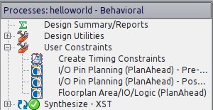
  1) In menu Tools/PlanAhead - Pre-synthesis or
  2) In the design windows, in User Constraints, just double click in I/O Pin Planning (PlanAhead) - Pre-synthesis In both cases, it will ask you to create an UCF file. Accept it by clicking Yes.


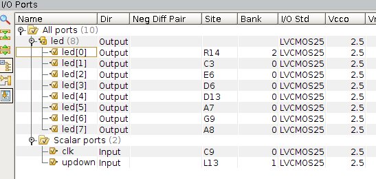
  You'll note a new file helloworld.ucf, double clicking it will open PlanAhead. We can see all ports that we have declared before:
  led(8) - output
  clk - input
  updown - input

  Now it's time to assign pins to signals. In this board we have:

  Led 0 - R14
  Led 1 - C3
  Led 2 - E6
  Led 3 - D6
  Led 4 - D13
  Led 5 - A7
  Led 6 - G9
  Led 7 - A8
  clock - C9
  updown - L13 (switch SW0)

  Here we can see in PlanAhead all pins assigned.


  Note that we have again two options. Using PlanAhead we can click in the Site column and chose which pin to use or ISE, double click in Edit Constraints (Text) and type all constraints. Normally I assing one by PlanAhead and copy the rest in text mode which I think is faster.
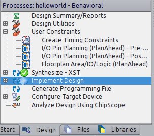
  Once done we can implement our design by clicking in Implement Design at Design tab in ISE.


  Now it's time to generate our programming file by clicking in Generate Programming File (durrr). Once done, we click in Configure Target Device which will opens Impact. It will ask you to create a new project file, just click Yes.
  Go to menu Edit/Launch Wizard. Select Configure devices using Boundary-Scan (JTAG) and select our helloworld.bit file. Bypass all 3 others devices. In the next window, check Pulse PROG, click in Apply and OK.


  In the image above we can see that our FPGA is assigned with helloworld.bit and the others 3 device were bypassed. Now right-click over the green FPGA and select Program.
  And it's done! (I really wish that your leds are blinking!!! LOL)
  
  Marcelo


Read more ►

FPGA hello world - Led blink - Part II

  Hello!
  In this post I'll show you how to simulate our hello world design.
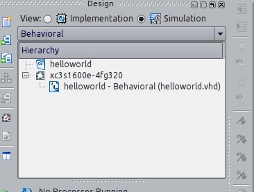
  In ISE, in Design tab, select View Simulation as in the image below


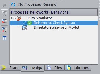
  Now we "compile" our design as usual. First we select in Hierarchy our helloworld entity and click first in Behavioral Check Syntax and then Simulate Behavioral Model.


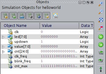
  After click in Simulate, a new program will be launch - ISim.We'll have all signals defined in our design there.

  We select all signals and we add them to wave window. We can drag and drop them or right clicking all selected signals and selection Add to wave window.
  We need to create our clock signal by right-clicking in clk signal and selecting Force Clock. In our case 50MHz has a 20ns period. We set our updown to 0 first and then to 1 to see what happens. Here I also changed blink_freq to 1000000 to be able to show you the results (1 Hz is an eternity for our FPGA). Click in run and that's it!


   We can see that we're decreasing our led value when updown = 0 and increasing when updown = 1. The updown value changes in the blue cursor.

  Next post, I'll show how to configurate our FPGA and finally see our leds blink!

 Bye
 Marcelo
Read more ►

Sunday, January 15, 2012

FPGA hello world - Led blink

  Hello guys!
  Let's do our first design using the demo board.

  I'll explain step-by-step how to create a new project, develop our code and synthesize it using ISE 13.3 installed in the last post.

  1) First we have to create a project.Go to File > New Project...
      Name: helloworld
      Top-level source type: HDL

  2) Then we have to select device
      Family: Spartan3E
      Device: XC3S1600E
      Package: FG320
      Speed: -4
      Simulator: Isim(VHDL/Verilog)
      Preferred Language: VHDL
      VHDL Source Analysis Standard: VHDL-200X

  3) Now at panel left "Design", right click over : xc3s1600e-4fg320 and select "New source..."
  4) Select "VHDL module" and type filename: helloworld.
  5) We don't need to enter right now the port name. We can define after in the code. Click NEXT and then FINISH.

  Now we can start make some code:

library IEEE;
use IEEE.STD_LOGIC_1164.ALL;

-- Uncomment the following library declaration if using
-- arithmetic functions with Signed or Unsigned values
use IEEE.NUMERIC_STD.ALL;

-- Uncomment the following library declaration if instantiating
-- any Xilinx primitives in this code.
--library UNISIM;
--use UNISIM.VComponents.all;

entity helloworld is
   port (clk : in STD_LOGIC := '0';
      led : out  STD_LOGIC_VECTOR (7 downto 0) := (others => '0');
      updown : in STD_LOGIC := '1'
      );
end helloworld;

architecture Behavioral of helloworld is
   constant CLK_FREQ : integer := 50000000;
   constant BLINK_FREQ : integer := 1;
   constant CNT_MAX : integer := CLK_FREQ/BLINK_FREQ/2-1;
   signal value : std_logic_vector (7 downto 0) := "00000000";
   signal cnt : unsigned (24 downto 0) := (others => '0');
begin

   process(clk)
  
   begin
      if rising_edge(clk) then
         if cnt = CNT_MAX then
            cnt <= (others =>'0');
            case updown is
               when '1' => value <= std_logic_vector(unsigned(value) + 1);
               when others => value <= std_logic_vector(unsigned(value) - 1);
            end case;
          
         else
            cnt <= cnt + 1;
         end if;
      end if;
   end process;
  
   led <= value;
  
end Behavioral;

This program is very simple. The leds will count in binary mode, upwards when updown is '1' and downwards when '0'.
At lines 1, 2 and 6, as like in C the #include statement. The STD_LOGIC_1164 define most of standard logic levels like high, low, Z, X, etc. The NUMERIC_STD is used to be able to use functions with signed and unsigned types.

We define our entity at line 13 and it has only 3 pins: clk, led and updown where clk and updown are input type and led an 8 bits output type.
As our circuit is a synchronized one, we will perform some action only in a rising edge of clock. It's done at line 28 with the reserved word rising_edge.
And finally, as our clock use a 50MHz crystal, we have to have a pre-scale counter to be able to see the leds changing, otherwise, we would see the 8 leds always on. We use for this purpose the signal cnt that counts from 0 until CNT_MAX.
Now, to synthesize our circuit, select View: Implementation and menu Process > Implement Top Module.


It will take a while because synthesize a circuit is very different of compiling a code. If you want to know more about, there are lots of sites out there that explains the difference. Just google it!
Next post I'll show you how to simulate our design, how to assign to the physical pins the signals that we defined in our code, how to generate the bitstream that will be programmed in the FPGA and finally how to program the FPGA demo board!

Marcelo
Read more ►